Home
› Outlet Wiring Diagram - Switched Outlet Wiring Diagram / It shows the components of the circuit as simplified shapes, and the capability and signal friends between the devices.
Outlet Wiring Diagram - Switched Outlet Wiring Diagram / It shows the components of the circuit as simplified shapes, and the capability and signal friends between the devices.
Outlet Wiring Diagram - Switched Outlet Wiring Diagram / It shows the components of the circuit as simplified shapes, and the capability and signal friends between the devices.. This repeats until the end of the chain. As shown in the fig, the switch is firstly installed in the wiring the hot wire from switch feeds all the other parallel connected outlets hence, the outlet on/off operation can be controlled through the switch. This is a polarized device. Strip 1 inch of insulation off of the black and white wires. Basics 17 tray & conduit layout drawing :
The long slot on the left is the neutral contact and the short slot is the hot contact. A grounded contact at the bottom, center is crescent shaped. A wiring diagram usually gives suggestion nearly the relative face and concord of devices and. If you aren't able to install electrical wiring behind walls due to ductwork or plumbing, an alternative solution is to conceal wires using a cable raceway, which runs along. The above diagram shows the gfci wiring to multiple outlet as in white while the pictures are same.
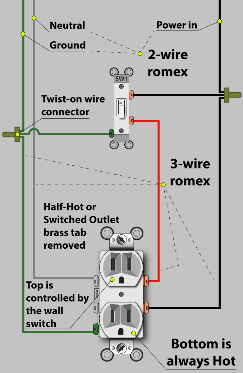
Wiring Diagrams For Switched Wall Outlets Do It Yourself Help Com from www.do-it-yourself-help.com It is the right wire for home wiring and for my needs in my shed. Want to turn a lamp on with a light switch? The long slot on the left is the neutral contact and the short slot is the hot contact. Troubleshooting dead outlets and what to do when gfci won t reset. Often the simplest approach is to run cables to either the attic directly above the new outlet or switch, or to a basement or crawl space below. All wires are spliced to a pigtail which is connected to each device separate from all the others in the row. Switched outlet wiring diagram depicts the electrical power from the circuit breaker panel entering the switched electrical receptacle outlet box where a two wire cable goes to the switch and another two wire cable feeds power to another outlet that is live at all times. Mar 09, 21 09:56 pm.
If you aren't able to install electrical wiring behind walls due to ductwork or plumbing, an alternative solution is to conceal wires using a cable raceway, which runs along.
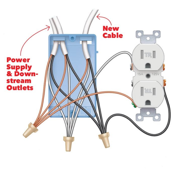
50 amp rv wiring is different than say a 50 amp clothes dryer outlet or an older stove outlet. All wires are spliced to a pigtail which is connected to each device separate from all the others in the row. Today we're wiring up a double duplex outle. This is a standard 15 amp, 120 volt wall receptacle outlet wiring diagram. The long slot on the left is the neutral contact and the short slot is the hot contact. Strip 1 inch of insulation off of the black and white wires. The black wire (line) and white (neutral) connect to the receptacle terminals and another 2 wire nm that travels to the next receptacle. For wiring in series, the terminal screws are the means for passing voltage from one receptacle to another. Installing an rv outlet at home is a great idea if you own a recreational vehicle or a camper. Symbols that represent the components of a circuit, and lines that represent the connections between them. The nec requires that dryers have a dedicated circuit with a minimum of 30 amps. Sometimes it is handy to have an outlet controlled by a switch. Understanding switched outlet wiring for home electrical applications the switched outlet wiring configurations show two different wiring scenarios which are most commonly used.
Light switch and outlet in the same box wiring diagrams to add a new for your on off diagram one two schematic wire switched half hot double gang do it nec gfci with. Basics 17 tray & conduit layout drawing : With easy to follow diagrams and instructions, you can have that convenience in no time. I became aware that it is against electrical codes to use sheathed cable inside a conduit. Step by step instructions on how to wire a switched outlet.
An Electrician Explains How To Wire A Switched Half Hot Outlet Dengarden from images.saymedia-content.com The above diagram shows the gfci wiring to multiple outlet as in white while the pictures are same. Want to turn a lamp on with a light switch? The long slot on the left is the neutral contact and the short slot is the hot contact. Today we're wiring up a double duplex outle. Step by step instructions on how to wire a switched outlet. In this wiring diagram, the builtin switch in the combo device controls a lighting point whereas, outlet can be used for other loads. Basics 16 wiring (or connection) diagram : Multiple outlet in serie wiring diagram :
Strip the outer insulation off of it for about 4 inches and separate the three wires inside.
Switched outlet wiring diagram depicts the electrical power from the circuit breaker panel entering the switched electrical receptacle outlet box where a two wire cable goes to the switch and another two wire cable feeds power to another outlet that is live at all times. Strip the outer insulation off of it for about 4 inches and separate the three wires inside. Often the simplest approach is to run cables to either the attic directly above the new outlet or switch, or to a basement or crawl space below. Light switch and outlet in the same box wiring diagrams to add a new for your on off diagram one two schematic wire switched half hot double gang do it nec gfci with. A wiring diagram usually gives suggestion nearly the relative face and concord of devices and. An electrician explains how to wire a switched half hot outlet dengarden. A wiring diagram is a schematic type that uses abstract illustrated symbols to show all of the components of a system. One side of the gfci connected to the ground (neutral wire as shown white in the diagram) and another side to the high potential (hot wire shown as black in the diagram) shows as in black color. Mar 09, 21 09:56 pm. Basics 13 valve limit switch legend : Multiple gfci outlet wiring diagram : Use tight wire nuts for cable and wire joints. However, working on your circuit breaker box and electrical system can lead to serious injury or death if you don't know what you're doing, so hire an electrician if you don.
A wiring diagram usually gives suggestion nearly the relative face and concord of devices and. An electrician explains how to wire a switched half hot outlet dengarden. All you will need is a 30 amp rv outlet (nema: In this wiring diagram, the builtin switch in the combo device controls a lighting point whereas, outlet can be used for other loads. Strip 1 inch of insulation off of the black and white wires.
Install A Super Easy Usb Outlet Diy Family Handyman from www.familyhandyman.com Basics 16 wiring (or connection) diagram : Basics 13 valve limit switch legend : The black wire (line) and white (neutral) connect to the receptacle terminals and another 2 wire nm that travels to the next receptacle. Troubleshooting dead outlets and what to do when gfci won t reset. One side of the gfci connected to the ground (neutral wire as shown white in the diagram) and another side to the high potential (hot wire shown as black in the diagram) shows as in black color. As shown in the fig, the switch is firstly installed in the wiring the hot wire from switch feeds all the other parallel connected outlets hence, the outlet on/off operation can be controlled through the switch. Strip 1 inch of insulation off of the black and white wires. Basics 14 aov schematic (with block included) basics 15 wiring (or connection) diagram :
Multiple gfci outlet wiring diagram :
Today we're wiring up a double duplex outle. Large rocker style switch panel wiring diagram. Sometimes it is handy to have an outlet controlled by a switch. For wiring in series, the terminal screws are the means for passing voltage from one receptacle to another. However, working on your circuit breaker box and electrical system can lead to serious injury or death if you don't know what you're doing, so hire an electrician if you don. Receptacle wiring in the diagram below a 2 wire nm cable supplies line voltage from the electrical panel to the first receptacle outlet box. Light switch and outlet in the same box wiring diagrams to add a new for your on off diagram one two schematic wire switched half hot double gang do it nec gfci with. This is a standard 15 amp, 120 volt wall receptacle outlet wiring diagram. A wiring diagram is a schematic type that uses abstract illustrated symbols to show all of the components of a system. You've never heard anyone complain about having too many outlets in a shop, office, kitchen, or other work space. Step by step instructions on how to wire a switched outlet. A wiring diagram usually gives suggestion nearly the relative face and concord of devices and. Any break or malfunction in one outlet will cause all the other outlets to fail.